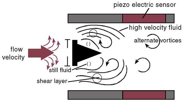
Principles of Operation
Vortices
are created when a fluid passes around a bluff body as shown in
illustration (click Images Tab above). Vortices are alternately shed on
each side of the body, 180 degrees out of phase to each other, resulting
in an oscillating pressure gradient. As flow increases the frequency of
vortices increases in proportion to the increased flow thereby creating
a linear relationship.
General Description
Constructed
of type 304 or 316 stainless steel, Vortex meters may be inserted into
pipe conduits carrying gases, liquids or steam. Insertion applications
facilitate inside diameters from 4” to 12 feet!
By porting
directly into piping, conduit lines need not be lengthened. Optional
isolation valve permits installation, servicing, or removal of vortex
meters without having to shut gas, liquid or steam processing
operations.
Key pad or communication interface is provided to access the following parameters:
measuring
units; programmable flow alarm; two programmable totalizers;
programmable flow rate pulse output; two programmable optically isolated
outputs; battery backed real time clock (RTC); digital communication
interface (RS-232 or RS-485); programmable diagnostic events log and
register with date/time stamp; programmable process variable log with
date/time stamp; calibration and flowing fluid parameters adjustment;
extensive diagnostics.
Aalborg's unique dual signal processing
technology independently measures each vortex on either side of the
bluff body and filters out non-flow noise. This results in less noise
and higher accuracy throughout the flow range.
User preset
temperature and pressure information processed by an on board computer
to calculate density and mass flow. Local 2x16 LCD readout provides
simultaneous volumetric and mass flow readings, total flow volume
reading in selectable engineering units, diagnostic events indication,
and password protected - user entered parameters.